
.png)
General Optical Fiber Communication System
Basic block diagram of optical fiber communication system consists of following important blocks.1. Transmitter
2. Information channel
3. Receiver..png)
.png)
Need of fiber optic communication
Fiber optic communication system has emerged as most important communication system. Compared to traditional system because of following requirements :
1. In long haul transmission system there is need of low loss transmission medium
2. There is need of compact and least weight transmitters and receivers.
3. There is need of increase span of transmission.
4. There is need of increased bit rate-distance product.
A fiber optic communication system fulfills these requirements, hence most widely acception.
Advantages of Optical Fiber Communications
1. Wide bandwidth The light wave occupies the frequency range between 2 x 10¹² Hz to 3.7 x 10¹² Hz. Thus the information carrying capability of fiber optic cables is much higher.
2. Low losses Fiber optic cables offers bery less signal attenuation over long distances. Typically it is less than 1 dB/km. This enables longer distance between repeaters.
3. Immune to cross talk Fiber optic cables has very high immunity to electrical and magnetic field. Since fiber optic cables are non-conductors of electricity hence they do not produce magnetic field. Thus fiber optic cables are immune to cross talk between cables caused by magnetic induction.
4. Interference immune Fiber optic cables are immune to conductive and radiative interferences caused by electrical noise sources such as lighting, electric motors, fluorescent lights.
5. Light weight As fiber cables are made of silica glass or plastic which is much lighter than copper or aluminium cables. Light weight fiber cables are cheaper to transport.
6. Small size The diameter of fiber is much smaller compared to other cables, therefore fiber cable is small in size, requires less storage space.
7. More strength Fiber cables are stronger and rugged hence can support more weight.
8. Security Fiber cables are more secure than other cables. It is almost impossible to tap into a fiber cable as they do not radiate signals. No ground loops exist between optical fibers hence they are more secure.
9. Long distance transmission Because of less attenuation transmission at a longer distance is possible.
10. Environment immune Fiber cables are more immune to environmental extremes. They can
12. Less cost Cost of fiber optic system is less compared to any other system.
2. Low losses Fiber optic cables offers bery less signal attenuation over long distances. Typically it is less than 1 dB/km. This enables longer distance between repeaters.
3. Immune to cross talk Fiber optic cables has very high immunity to electrical and magnetic field. Since fiber optic cables are non-conductors of electricity hence they do not produce magnetic field. Thus fiber optic cables are immune to cross talk between cables caused by magnetic induction.
4. Interference immune Fiber optic cables are immune to conductive and radiative interferences caused by electrical noise sources such as lighting, electric motors, fluorescent lights.
5. Light weight As fiber cables are made of silica glass or plastic which is much lighter than copper or aluminium cables. Light weight fiber cables are cheaper to transport.
6. Small size The diameter of fiber is much smaller compared to other cables, therefore fiber cable is small in size, requires less storage space.
7. More strength Fiber cables are stronger and rugged hence can support more weight.
8. Security Fiber cables are more secure than other cables. It is almost impossible to tap into a fiber cable as they do not radiate signals. No ground loops exist between optical fibers hence they are more secure.
9. Long distance transmission Because of less attenuation transmission at a longer distance is possible.
10. Environment immune Fiber cables are more immune to environmental extremes. They can
operate over a large temperature variations. Also they are not affected by corrosive liquids and gases.
11. Sage and easy installation Fiber cables are safer and easier to install and maintain. They are nonconductors hence there is no shock hazards as no current or voltage is associated with them. Their small size and light weight feature makes installation easier.
12. Less cost Cost of fiber optic system is less compared to any other system.
Disadvantages of Optical Fiber Communications
1. High initial cost The initial cost of installation or setting up cost is very high compared to all
other system.
2. Maintenance and repairing cost The maintenance and repairing of fiber optic systems is not only difficult
but expensive also.
3. Jointing and test procedures Since optical fibers are of very small size. The fiber joining process is very
costly and requires skilled manpower.
4. Tensile stress Optical fibers are more susceptible to buckling, bending and tensile stress
than copper cables. This leads to restricted practice to use optical fiber
technology to premises and floor backbones with a few interfaces to the
copper cables.
5. Short links Even though optical fiber cables are inexpensive, it is still not cost effective to
replace every small conventional connector (e.g. between computers and
peripherals), as the price of optoelectronic transducers are very high.
6. Fiber losses The amount of optical fiber available to the photodetector at the end of
fiber length depends on various fiber losses such as scattering, dispersion,
attenuation and reflection.
Applications of Optical Fiber Communications
- Urban broadband service networks
- Used in telephone systems
- Used in sub-marine cable networks
- Used in data link for computer networks, CATV Systems
- Used in CCTV surveillance cameras
- Used for connecting fire, police, and other emergency services.
- Used in hospitals, schools, and traffic management systems.
- They have many industrial uses and also used for in heavy duty constructions.
Optical Fiver as Waveguide
An optical fiber is a cylindrical dielectric waveguide capable of conveying electromagnetic waves at optical frequencies. The electromagnetic energy is in the form of the light and propagates along the axis of the fiber. The structural of the fiver determines the transmission characteristics.The propagation of light along the waveguide is decided by the modes of the waveguides, here mode means path. Each mode has distict pattern of electric and magnetic field distributions along the fiber length. Only few modes can satisfy the homogeneous wav equation in the fiver also the boundary condition a waveguide surfaces. When there is only one path for light to follow then it is called as single mode propagation. When there is more than one path then it is called as multimode propagation.
.png)
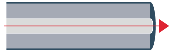
A single fiber structure is shown in Fig. It consists of a solid dielectric cylinder with radius ‘a’. This cylinder is called as core of fiber. The core is surrounded by dielectric, called cladding. The index of refraction of core (glass fiber) is slightly greater than the index of refraction of cladding. If refractive index of core (glass fiver) = n1 and refractive index of cladding = n2 then n1 > n2.
Single fiber structure
.png)
Propagation in Optical Fiber
To understand the general nature of light wave propagation in optical fiber. We first consider the construction of optical fiber. The innermost is the glass core of very thin diameter . The light wave can propagate along such a optical fiber. Single mode fibers are capable of carrying only one signal of a specific wavelength.In multimode propagation the light propagates along the fiber in zigzag fashion, provided it can undergo total internal reflection (TIR) at the core cladding boundaries.
Total internal reflection at the fiber wall can occur only if two conditions are satisfied.
Condition 1:
The index of refraction of glass fiber must be slightly greater than the index of refraction of material surrounding the fiber (cladding). If refractive index of glass fiber = n1 and refractive index of cladding = n2 then n1 > n2.
Condition 2 :
The angle of incidence of light ray must be greater than critical angle .
.png)
A light beam is focused at one end of cable. The light enters the fibers at different angles. Fig. shows the conditions exist at the launching end of optic fiber. The light source is surrounded by air and the refractive index of air is n0 = 1. Let the incident ray makes an angle ϕ0 with fiber axis. The ray enters into glass fiber at point P making refracted angle ϕ1 to the fiber axis, the ray is then propagated diagonally down the core and reflect from the core wall at point Q. When the light ray reflects off the inner surface, the angle of incidence is equal to the angle of reflection, which is greater than critical angle.
In order for a ray of light to propagate down the cable, it must strike the core cladding interface at an angle that is greater than critical angle (ϕc).
Acceptance Angle
Acceptance angle is the maximum angle at which a fiber optic cable can accept incoming light and transmit it without significant loss. It is an important parameter in determining the maximum amount of light that can be transmitted through an optical fiber..png)
Acceptance Cone
Rotating the acceptance angle around the fiber axis, a cone shaped
pattern is obtained, it is called as acceptance cone of the fiber input.
.png)
Numerical Aperture (NA)
The numerical aperture (NA) of a fiber is a figure of merit which represents
its light gathering capability. Larger the numerical aperture, the greater
the
amount of light accepted by fiber. The acceptance angle also determines how
much light is able to be enter the fiber and hence there is relation between the
numerical aperture and the cone of acceptance.
.png)
Types of Rays
1. The skew rays does not pass through the center, as show in Fig.a. The skew rays reflects off from the core cladding boundaries and again
bounces around the outside of the core. It takes somewhat similar shape of
spiral of helical path.
2. The meridional ray enters the core and passes through its axis. When the
core surface is parallel, it will always be reflected to pass through the enter.
The meridional ray is shown in fig. (b).
3. The axial ray travels along the axis of the fiber and stays at the axis all the
time. It is shown in fig. (c).
.png)
Types of optical fiber
There are two primary types of fiber, each of which has a different application. These are multimode (MM) fiber, which has a large core and allows for multiple paths through the fiber, and single-mode (SM) fiber, which has only one path, through a much smaller core.1. Multimode optical fiber
Multimode fiber optic cable allows multiple modes of light to pass through a large core, which in turn increases the number of reflections as the light passes through. The advantage of this type of fiber is that lower-cost transceivers can be used, but it also introduces a lot of dispersion and attenuation. In short, it means that the size of the core leaves so much room for light to bounce as it’s sent down the fiber that the quality of the signal degrades quickly. It also can’t be amplified, which means that it is only suitable for short distances where simpler and cheaper transceivers can be used. I.e., where a low-cost solution is needed.For any distance greater than 200-300 meters, the multimode fiber isn’t suitable. It’s most frequently found where these short distances are all that is needed, such as inside a data center. An example of this is OM4 fiber, capable of handling 10 and 100G traffic signals up to 100 meters.
There are two main types of multimode fiber:
i. Gradient-Index Multimode Fiber
This is the more common type of multimode fiber in use today. With the gradient-index multimode fiber, the light traveling close to the axis travels more slowly than the light near the cladding, which results in better grouping of the light rays. The refractive index, then, diminishes gradually from the center axis out toward the cladding.
ii. Step-Index Multimode Fiber
In this type of multimode fiber, the light travels in various zigzag and direct routes, bouncing off of the cladding. The result is that different “modes” of light arrive at different times at the other end of the fiber. When the different modes begin to spread out, the signal loses some of its shape.
2. Single-mode optical fiber
A single-mode optical fiber has a smaller core than multimode fiber and allows only one mode of light to travel through. Because there are fewer light reflections this type has the lowest signal attenuation, and the light can travel farther. It interfaces with single-mode optics, which uses lasers as a source of light, sending a single wavelength in a straight line down the fiber. It still has the same 125µm cladding as the multimode fiber, but the core is typically 9µm, instead of 50µm or more.Single-mode fiber has a higher bandwidth and is the most suitable type of fiber for long-distance networking. It, too, comes in several types, optimized for different regions in the fiber.
Fiber Profiles
A fiber is characterized by its profile and by its core and cladding diameters. One way of classifying the fiber cables is according to the index profile at
fiber. The index profile is a graphical representation of value of refractive
index across the core diameter.
There are two basic types of index profiles.
i) Step index fiber. ii) Graded index fiber.
.png)
Step Index (SI) Fiber
The step index (SI) fiber is a cylindrical waveguide core with central or inner core has a uniform refractive index of n1 and the core is surrounded by outer cladding with uniform refractive index of n2. The cladding refractive index (n2) is less than the core refractive index (n1). But there is an abrupt change in the refractive index at the core cladding interface. Refractive index profile of step indexed optical fiber is shown in Fig.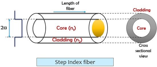
Graded Index (GRIN) Fiber
The graded index fiber has a core made from many layers of glass. In the graded index (GRIN) fiber the refractive index is not uniform within
the core, it is highest at the center and decreases smoothly and continuously
with distance towards the cladding. The refractive index profile across the
core takes the parabolic nature. Fig shows refractive index profile of
graded index fiber.
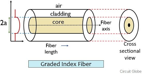
A graded index fiber has lower coupling efficiency and higher bandwidth than the step index fiber.
Optic Fiber Configurations
Depending on the refractive index profile of fiber and modes of fiber
there exist three types of optical fiber configurations.
These optic-fiber
configurations are -
i) Single mode step index fiber.
ii) Multimode step index fiber.
iii) Multimode graded index fiber.
Mode Field Diameter and Spot Size
The mode filed diameter is fundamental parameter of a single mode
fiber. This parameter is determined from mode field distributions of
fundamental
LP01 mode.
In step index and graded single mode fibers, the field amplitude distribution
is approximated by Gaussian distribution. The mode Field diameter (MFD) is distance
between opposite 1/e – 0.37 times the near field strength )amplitude) and power is
1/e2 = 0.135 times
In single mode fiber for fundamental mode, on field amplitude
distribution the mode filed diameter is shown in fig
.png)
.png)


Post a Comment
0 Comments