
What is communication?
Communication means signal transfer from the transmitter that passes through a medium; then, the output is obtained at the receiver.
What is Noise?
Noise is an unwanted signal, which interferes with the original message signal and corrupts the parameters of the message signal.What is sampling?
The process of obtaining a sample set from a continuous function of time x(t) is known as sampling.
State the sampling theorem
The sampling theorem states that, while taking the samples of a signal, it has to be taken specific care that the sampling rate is equal to or greater than the cut-off frequency along with the minimum sampling rate.
Signal-to-Noise Ratio (SNR) is the ratio of the signal power to noise power. The higher the value of SNR, the greater will be the quality of the received output.
Signal to Noise Ratio
Signal-to-Noise Ratio (SNR) is the ratio of the signal power to noise power. The higher the value of SNR, the greater will be the quality of the received output.What is the passband?
The passband is a range of wavelengths or frequencies that can pass through a filter without being attenuated.
Explain RF?
RF is a Radiofrequency which is a rate or frequency of oscillation within the range of about 3 Hz to 300 GHz.
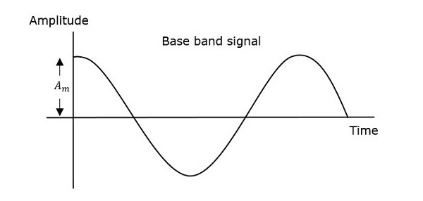
Modulation
Modulation is the process of changing the parameters of the carrier signal, in accordance with the instantaneous values of the modulating signal.
Following are some of the advantages for implementing modulation in the communication systems.
Advantages of Modulation
The antenna used for transmission, had to be very large, if modulation was not introduced. The range of communication gets limited as the wave cannot travel a distance without getting distorted.Following are some of the advantages for implementing modulation in the communication systems.
- Reduction of antenna size
- No signal mixing
- Increased communication range
- Multiplexing of signals
- Possibility of bandwidth adjustments
- Improved reception quality
Types of Modulation
There are many types of modulations. Depending upon the modulation techniques used, they are classified as shown in the following figure.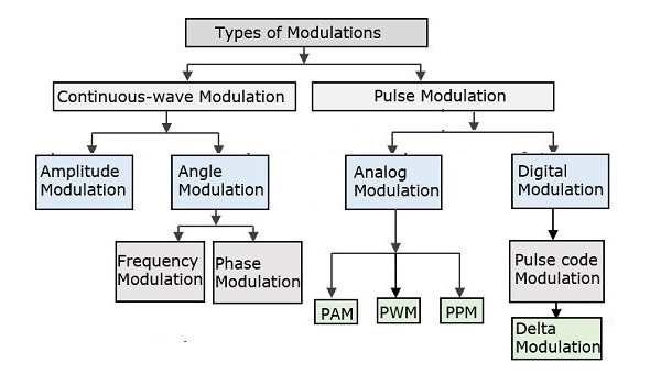
There are many three types of modulation:
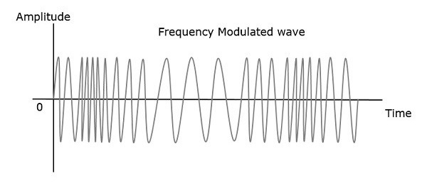
Frequency Modulation
When the frequency of a carrier wave changes or varies due to the change of the frequency of the signal modulation while the amplitude and frequency are at a constant state, we term it as Frequency modulation.
Narrowband FM
This frequency modulation has a small bandwidth when compared to wideband FM.The modulation index β is small, i.e., less than 1.
Its spectrum consists of the carrier, the upper sideband and the lower sideband.
This is used in mobile communications such as police wireless, ambulances, taxicabs, etc.
Wideband FM
This frequency modulation has infinite bandwidth.The modulation index β is large, i.e., higher than 1.
Its spectrum consists of a carrier and infinite number of sidebands, which are located around it.
This is used in entertainment, broadcasting applications such as FM radio, TV, etc.
Phase Modulation
When the phase of a high-frequency carrier wave changes or varies due to the change of the phase of the signal modulation while the amplitude and frequency are at a constant state, we term it as Phase modulation.
Amplitude Modulation
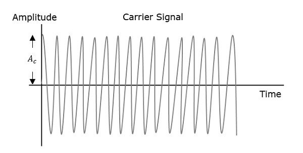
When the amplitude of a high-frequency carrier wave changes or varies due to the change of the amplitude of the signal modulation while the phase and frequency are at a constant state, we term it as Amplitude modulation.

The following two modulators generate AM wave.
- Square law modulator
- Switching modulator
The following demodulators (detectors) are used for demodulating AM wave.
- Square Law Demodulator
- Envelope Detector
In the process of Amplitude Modulation, the modulated wave consists of the carrier wave and two sidebands. The modulated wave has the information only in the sidebands. Sideband is nothing but a band of frequencies, containing power, which are the lower and higher frequencies of the carrier frequency.
The transmission of a signal, which contains a carrier along with two sidebands can be termed as Double Sideband Full Carrier system or simply DSBFC. It is plotted as shown in the following figure.
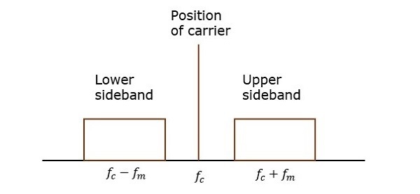
However, such a transmission is inefficient. Because, two-thirds of the power is being wasted in the carrier, which carries no information.
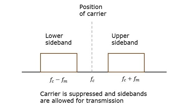
If this carrier is suppressed and the saved power is distributed to the two sidebands, then such a process is called as Double Sideband Suppressed Carrier system or simply DSBSC.
The following two modulators generate DSBSC wave.
- Balanced modulator
- Ring modulator
- Coherent Detector
- Costas Loop
Coherent Detector
Here, the same carrier signal (which is used for generating DSBSC signal) is used to detect the message signal. Hence, this process of detection is called as coherent or synchronous detection. Following is the block diagram of the coherent detector.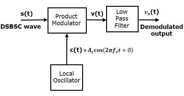
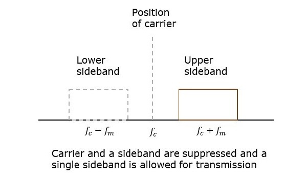
The process of suppressing one of the sidebands along with the carrier and transmitting a single sideband is called as Single Sideband Suppressed Carrier system or simply SSBSC. It is plotted as shown in the following figure.
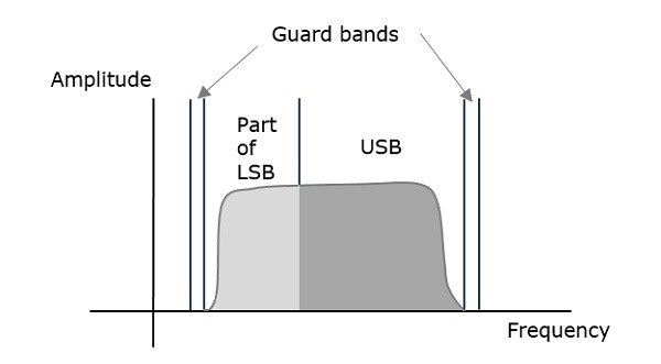
VSBSC Modulation is the process, where a part of the signal called as vestige is modulated along with one sideband. The frequency spectrum of VSBSC wave is shown in the following figure.
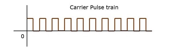
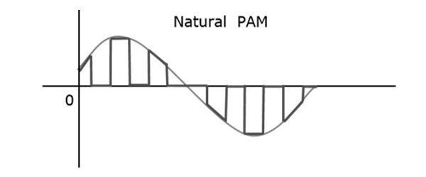
Pulse Amplitude Modulation
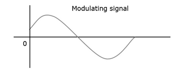
In Pulse Amplitude Modulation (PAM) technique, the amplitude of the pulse carrier varies, which is proportional to the instantaneous amplitude of the message signal.The pulse amplitude modulated signal will follow the amplitude of the original signal, as the signal traces out the path of the whole wave. In natural PAM, a signal sampled at Nyquist rate can be reconstructed, by passing it through an efficient Low Pass Filter (LPF) with exact cutoff frequency.
The following figures explain the Pulse Amplitude Modulation.
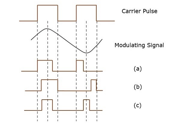
Pulse Width Modulation
In Pulse Width Modulation (PWM) or Pulse Duration Modulation (PDM) or Pulse Time Modulation (PTM) technique, the width or the duration or the time of the pulse carrier varies, which is proportional to the instantaneous amplitude of the message signal.The width of the pulse varies in this method, but the amplitude of the signal remains constant. Amplitude limiters are used to make the amplitude of the signal constant. These circuits clip off the amplitude to a desired level, and hence the noise is limited.
The following figure explains the types of Pulse Width Modulations.
Demodulation
Demodulation is getting the original form of data modulated carrier wave. To recover the data from a modulator carrier wave – a demodulator signal circuit comes in use.

What is a base station?
A base station is a radio transmitter or receiver that serves as the hub of the local wireless network.
What is an Amplifier?
An Amplifier is an electrical circuit or electronic device that is utilized for boosting or amplifying the power, current, or voltage of an applied signal.
What is crosstalk?
What is crosstalk?
Crosstalk is a disturbance caused by the electric or magnetic fields of one telecommunication signal affecting a signal in an adjacent circuit.
Differentiating between Modulation and Demodulation
While modulation helps in the collection of data into the carrier, demodulation helps in the recovery of data. However, there are a few distinguishable difference between both of them as a whole.
In a communication system modulation is done at the transmitter side. Whereas Demodulation is done at the receiver side of a communication system.
In modulation, the original message signal is mixed with a carrier wave whose parameters are required to be changed. In demodulation, the combination of carrier and message signal are separated from each other, to have an original information signal.
Modulation essentially occurs to transmit data to a longer distance. Demodulation takes place to retain the original form of the signal
What is Pulse Amplitude Modulation?
Pulse amplitude modulation is the basic form of pulse modulation. In this modulation, the signal is sampled at regular intervals and each sample is made proportional to the amplitude of the modulating signal. Before we study in detail PAM lets us know the concepts of modulation.
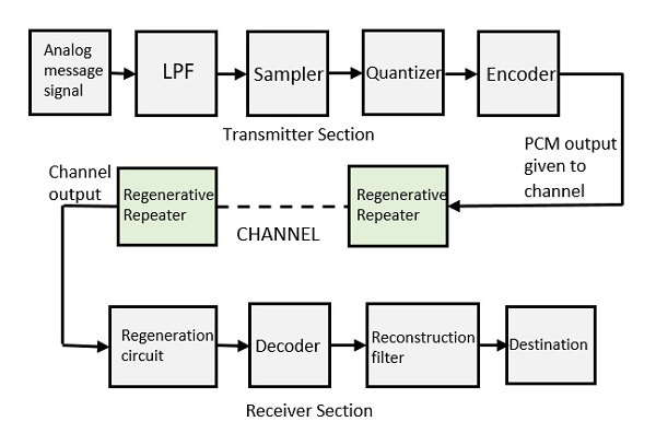
Pulse Code Modulation
When a digital signal undergoes Pulse Code Modulation, it converts the analog information into a binary sequence (1 and 0).What is quantization in digital communication?
Quantization is the process of mapping continuous infinite values to a smaller set of discrete finite values.
There are 3 types of Line Coding
Types of Line Coding
There are 3 types of Line CodingUnipolar
Polar
Bi-polar
Polar
Bi-polar
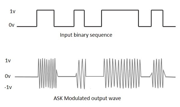
ASK
The short form of Amplitude Shift Keying is referred as ASK. It is the digital modulation technique. In this technique, amplitude of the RF carrier is varied in accordance with baseband digital input signal.
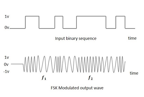
FSK
The short form of Frequency Shift Keying is referred as FSK. It is also digital modulation technique. In this technique, frequency of the RF carrier is varied in accodance with baseband digital input.PSK
The short form of Phase Shift Keying is referred as PSK. It is digital modulation technique where in phase of the RF carrier is changed based on digital input.BPSK
Binary Phase-shift keying (BPSK) is a digital modulation scheme that conveys data by changing, or modulating, two different phases of a reference signal (the carrier wave).Quadrature Phase Shift Keying (QPSK) is a form of Phase Shift Keying in which two bits are modulated at once, selecting one of four possible carrier phase shifts (0, 90, 180, or 270 degrees).
Frequency-shift keying (FSK) is a method of transmitting digital signals using discrete signals. The two binary states -- logic 0 (low) and 1 (high)
MSK
Minimum Shift Key Modulation is another type of digital modulation technique used to convert a digital signal into analog signals. It is also called Minimum-shift keying (MSK)Multiplexing
Multiplexing is the process of combining multiple signals into one signal, over a shared medium. If the analog signals are multiplexed, then it is called as analog multiplexing. Similarly, if the digital signals are multiplexed, then it is called as digital multiplexing.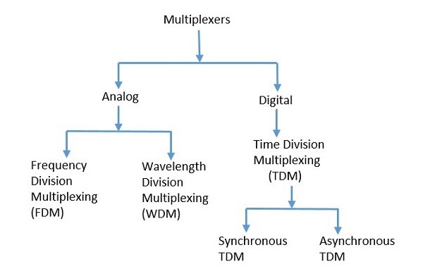
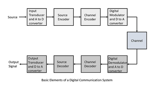
Elements of Digital Communication
The elements which form a digital communication system is represented by the following block diagram for the ease of understanding.
Pulse Code Modulation
A signal is pulse code modulated to convert its analog information into a binary sequence, i.e., 1s and 0s. The output of a PCM will resemble a binary sequence. The following figure shows an example of PCM output with respect to instantaneous values of a given sine wave.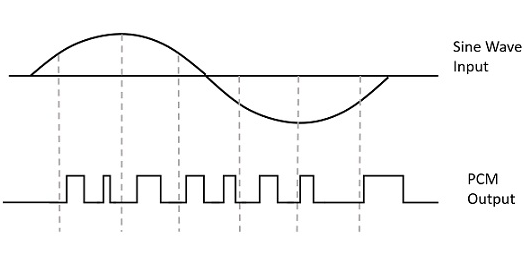
DPCM Transmitter
The DPCM Transmitter consists of Quantizer and Predictor with two summer circuits. Following is the block diagram of DPCM transmitter.Delta Modulation
The type of modulation, where the sampling rate is much higher and in which the stepsize after quantization is of a smaller value Δ, such a modulation is termed as delta modulation.
Inter Symbol Interference
This is a form of distortion of a signal, in which one or more symbols interfere with subsequent signals, causing noise or delivering a poor output.Causes of ISI
The main causes of ISI are −Multi-path PropagationNon-linear frequency in channels
Amplitude Shift Keying
Amplitude Shift Keying ASK is a type of Amplitude Modulation which represents the binary data in the form of variations in the amplitude of a signal.Any modulated signal has a high frequency carrier. The binary signal when ASK modulated, gives a zero value for Low input while it gives the carrier output for High input.
The following figure represents ASK modulated waveform along with its input.
Frequency Shift Keying
Frequency Shift Keying FSK is the digital modulation technique in which the frequency of the carrier signal varies according to the digital signal changes. FSK is a scheme of frequency modulation.The output of a FSK modulated wave is high in frequency for a binary High input and is low in frequency for a binary Low input. The binary 1s and 0s are called Mark and Space frequencies.
The following image is the diagrammatic representation of FSK modulated waveform along with its input.
Phase Shift Keying PSK is the digital modulation technique in which the phase of the carrier signal is changed by varying the sine and cosine inputs at a particular time. PSK technique is widely used for wireless LANs, bio-metric, contactless operations, along with RFID and Bluetooth communications.


Post a Comment
0 Comments